HartRAO Home >
DSS51 History >
DSS51 Upgrades
Deep Space Station 51 Antenna Upgrades
Click on the image for large version
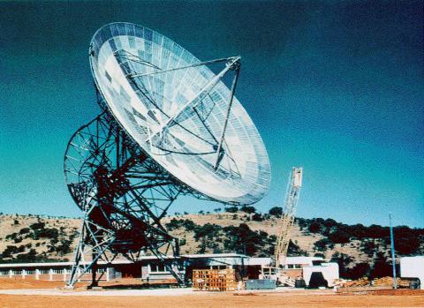
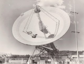
The
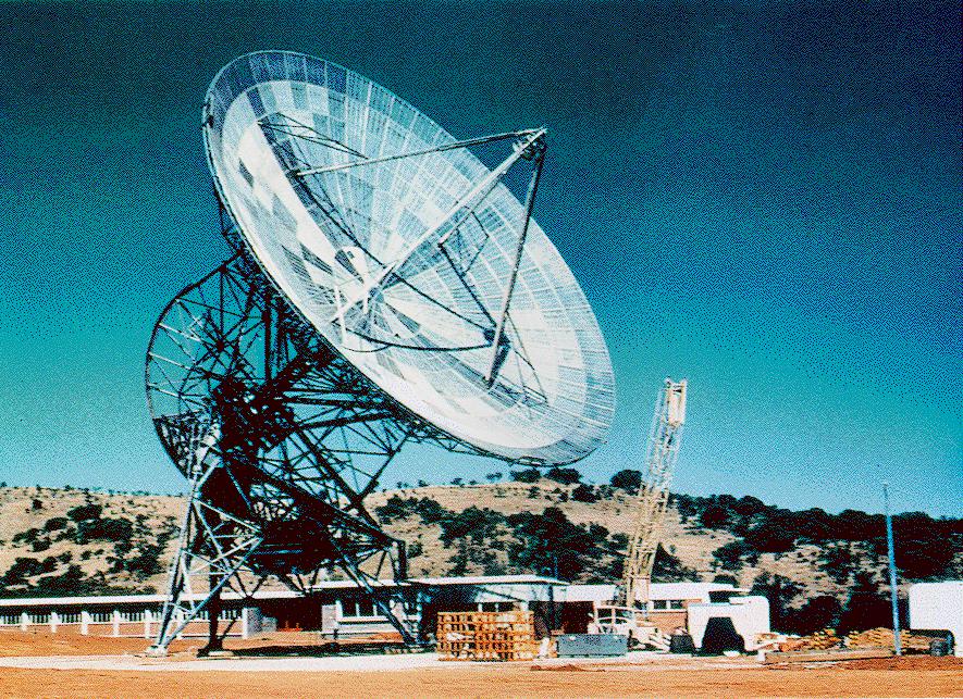
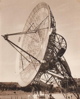
photograph above (courtesy JPL) shows the appearance of the telescope
shortly after completion, with a light tubular aluminium quadripod supporting the 960-MHz
microwave feed mounted at the primary focus. In its original form, the moving mass
of the antenna was about 100 tons.
Click on the image for large version

Click on the image for large version
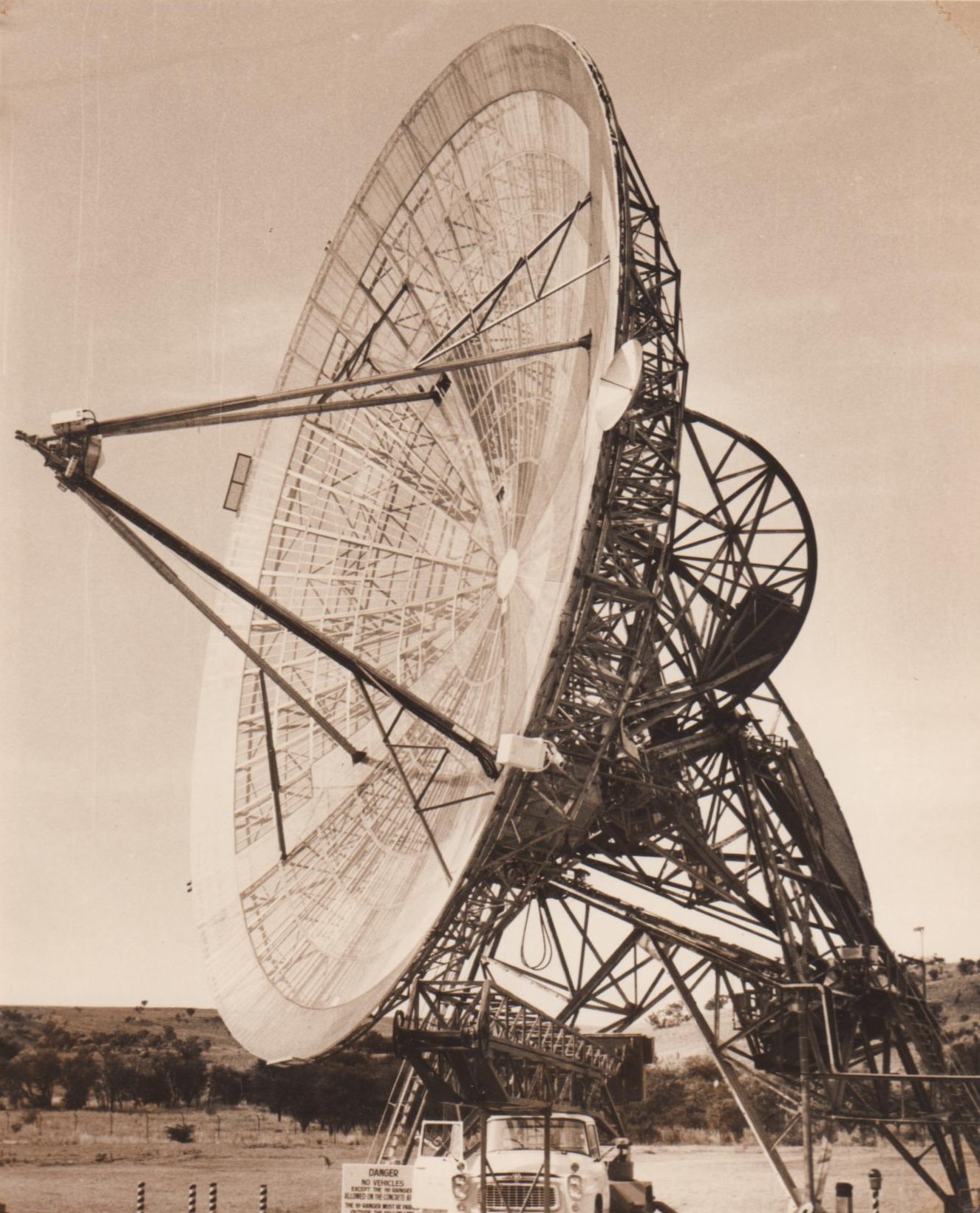
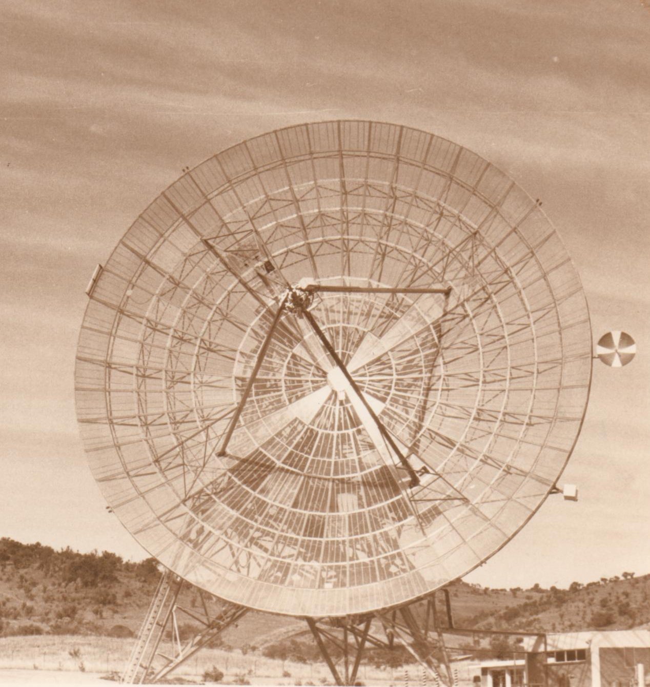
Two photos of the antenna taken in 1963 May. A small acquisition antenna
has been added on the side of the main antenna.
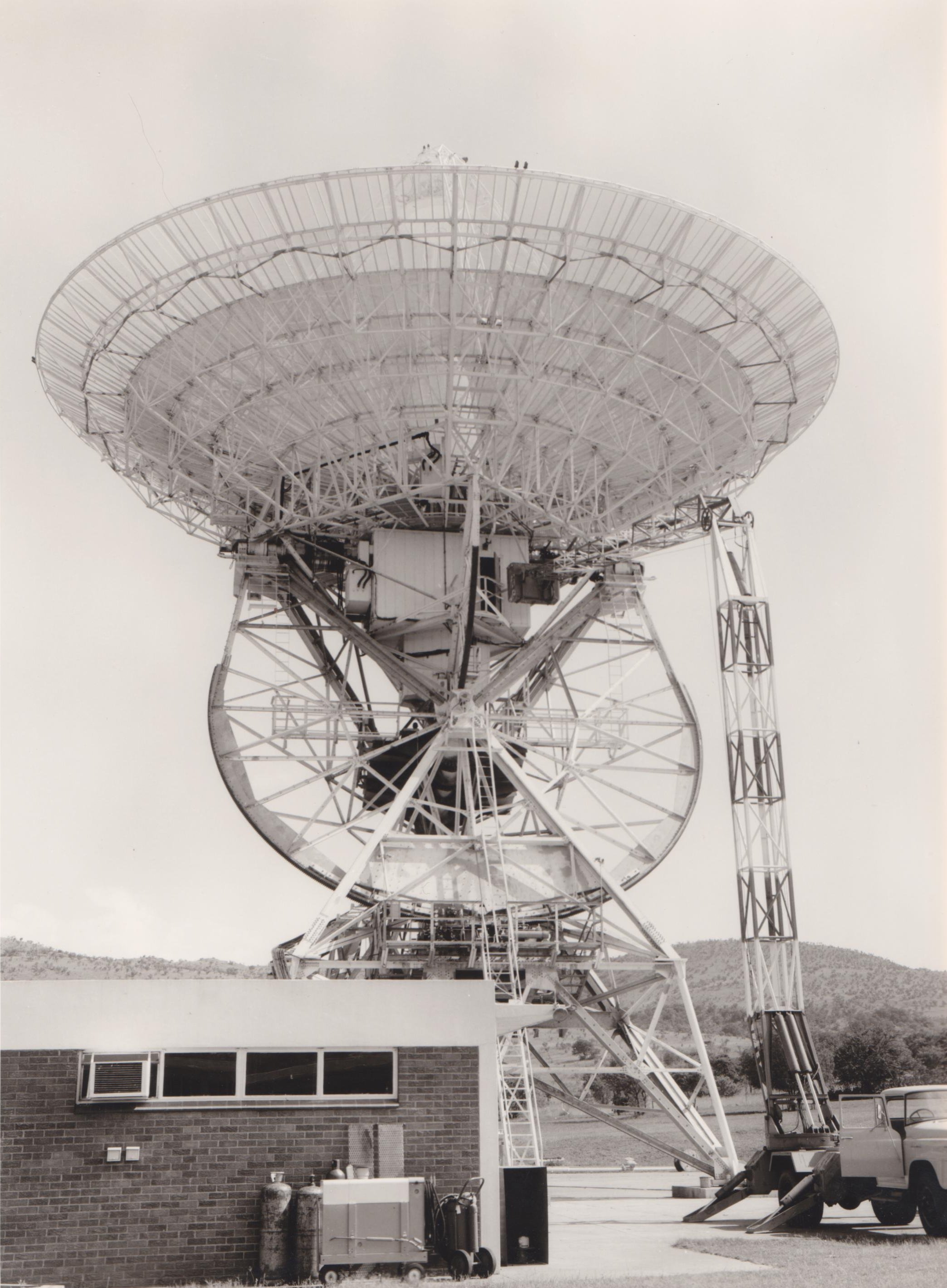
Cassegrain Conversion and S-band Upgrade, 1964
The first big upgrade took place in 1964, when the antenna was modified to a
Cassegrain feed and the Declination Equipment Room was added. The operating
frequency was changed to 2300 MHz, i.e. a wavelength of 13 cm, or "S-band",
using radar terminology. The
amplifier for the 2300 MHz receiver was a ruby maser, cooled to 4 Kelvins
(degrees above absolute zero, which is at -273 Celcius) in a helium
refrigerator. The prime focus microwave feed was replaced by a Cassegrain
reflector system, in which a convex hyperbolic mirror in front of the
primary focus reflected the 13-cm wavelength microwaves into a feed horn
inside a conical turret. The previous tubular aluminium quadripod legs were
replaced with lattice legs to supporting the new subreflector. With this
upgrade there was a 10 kW klystron transmitter in the Declination room, plus
substantially more equipment than we now have. In fact at one stage there
were two 10 kW klystron transmitters - one at 890 MHz and one at 2200 MHz.
Owing to the amount of lead weight counterbalance that was needed, the total
moving mass of the antenna was increased to about 200 tons.
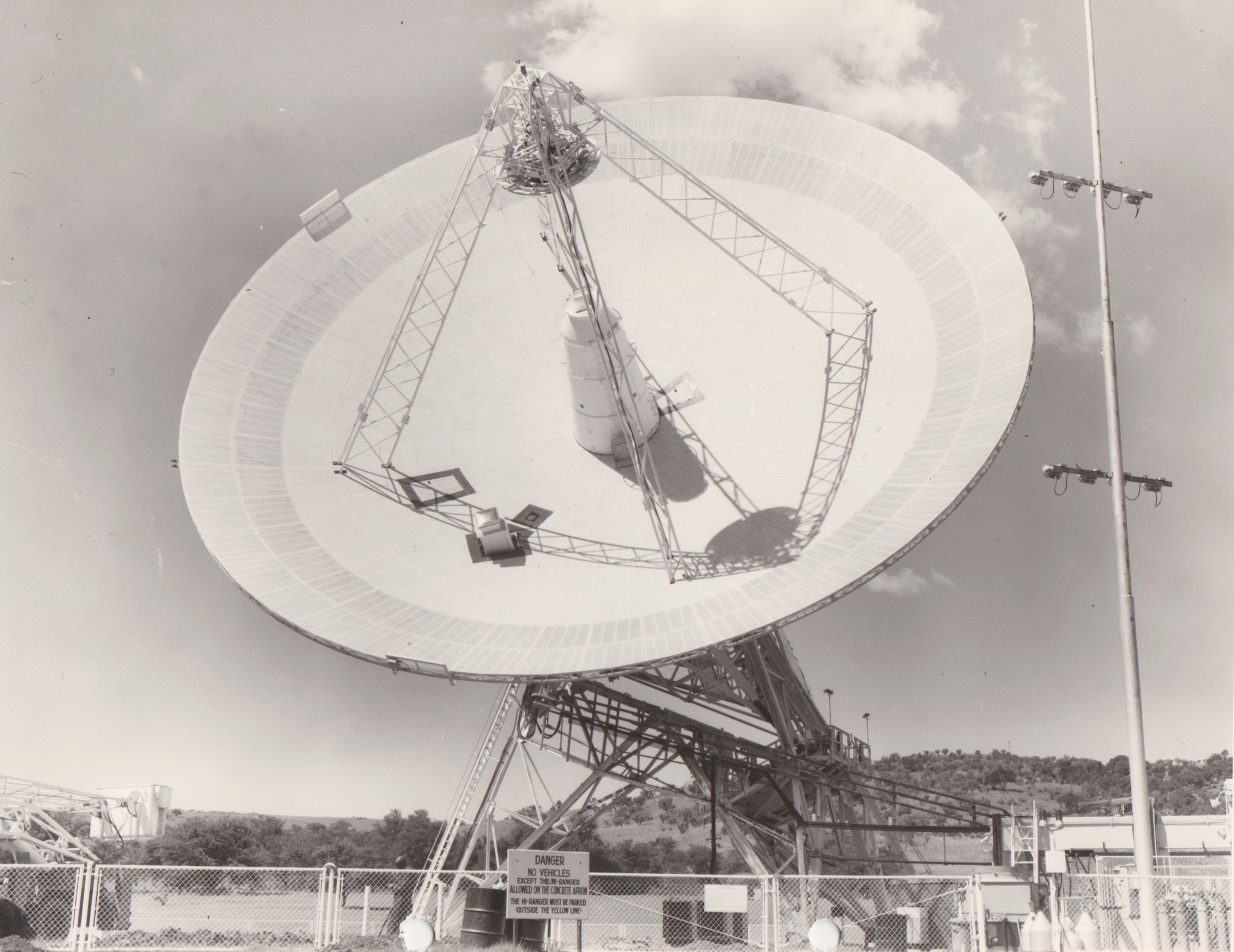
Click on the image for large version
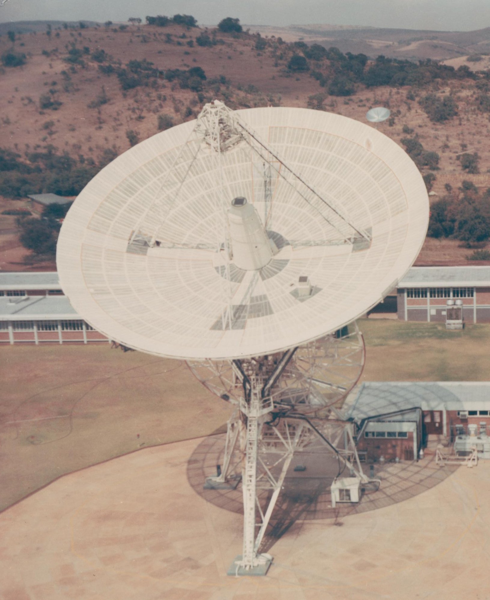
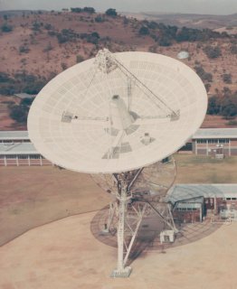
Airborne photo of the antenna from the north in 1966 May, showing the
Cassegrain feed cone and latticework legs supporting the subreflector.
Click on the image for large version
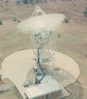
Airborne photo of the antenna from the south in 1966 May. The shadow of the
antenna reveals that the surface is still mesh, although now painted white
instead of bare aluminium as built.
The 1966 photographs above show the big change in appearance that resulted from
the the S-band upgrade.
Click on the image for large version
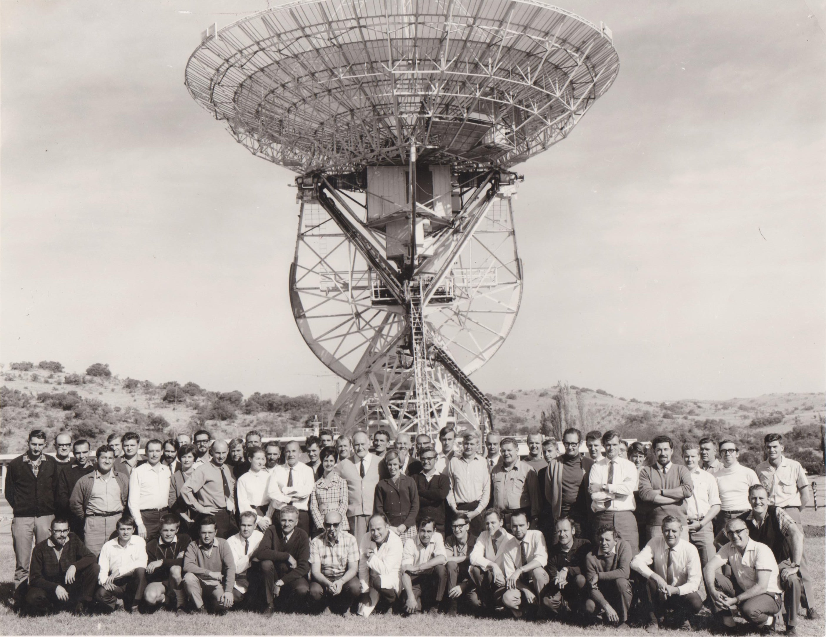
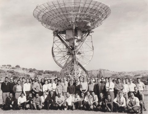
Undated staff photo taken between the S-band conversion of 1964 and
the surface replacement of 1968.
Surface Upgrade, 1968
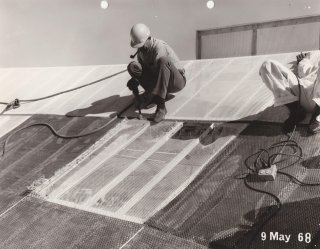
The second major upgrade took place in 1968 and was the replacement of
the mesh surface with perforated aluminium plates. The perforations
consisted of holes of 1cm diameter. The inner 20 metres used 2mm thick
plates with 25% porosity and the outermost two rings used 2mm plates with
50% porosity. The rms error of the surface from the true paraboloidal shape
was then about 2mm. S-band aperture efficiency improved by about 10% as a
result of the resurfacing.
Click on the image for large version
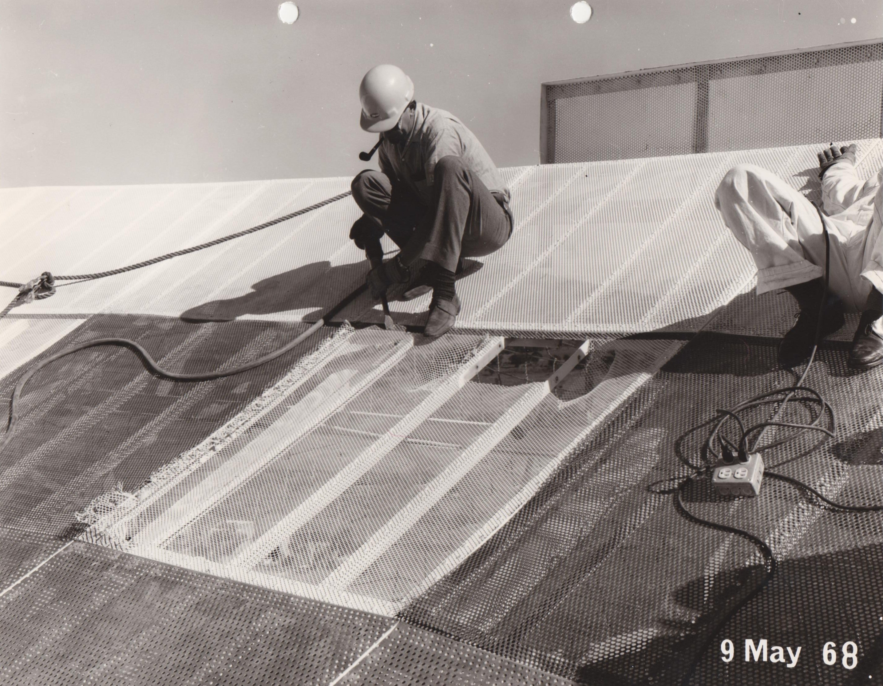
Antenna technician Joe Pheiffer levers up the old mesh surface, 1968 May 09. The
unpainted panels alongside are the new perforated plates.
Click on the image for large version
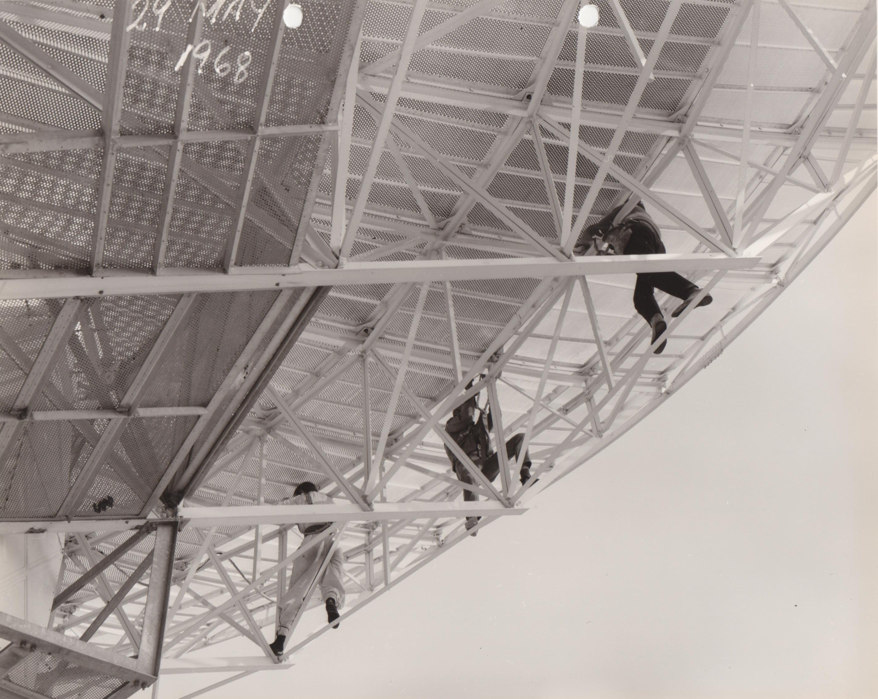
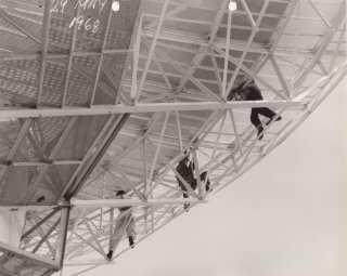
Working on the new antenna surface, seen from below, 1968 May 29.
Click on the image for large version
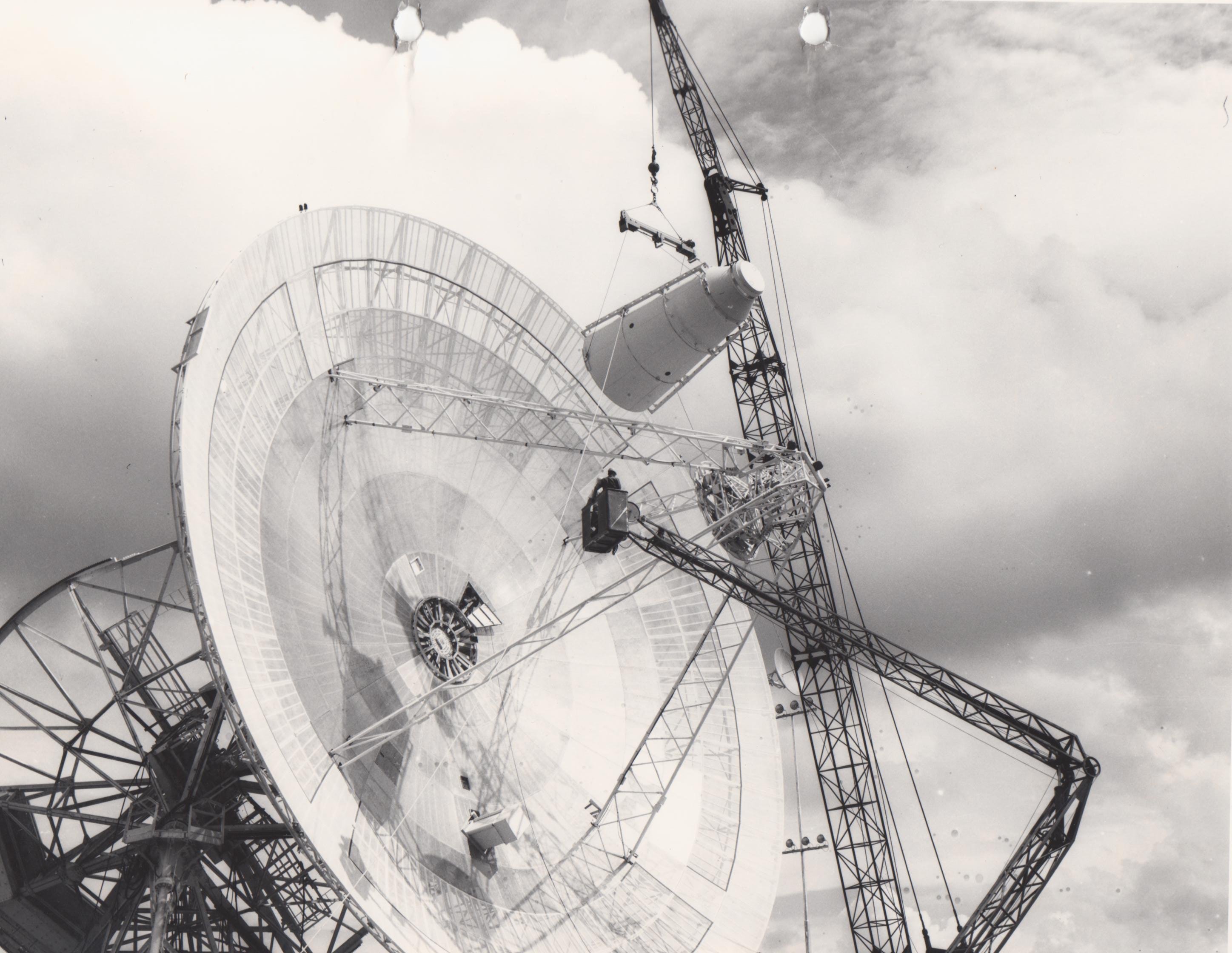
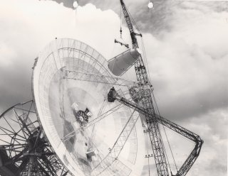
During the surface replacement operation the Cassegrain cone was removed, on
1968 June 03.
Click on the image for large version
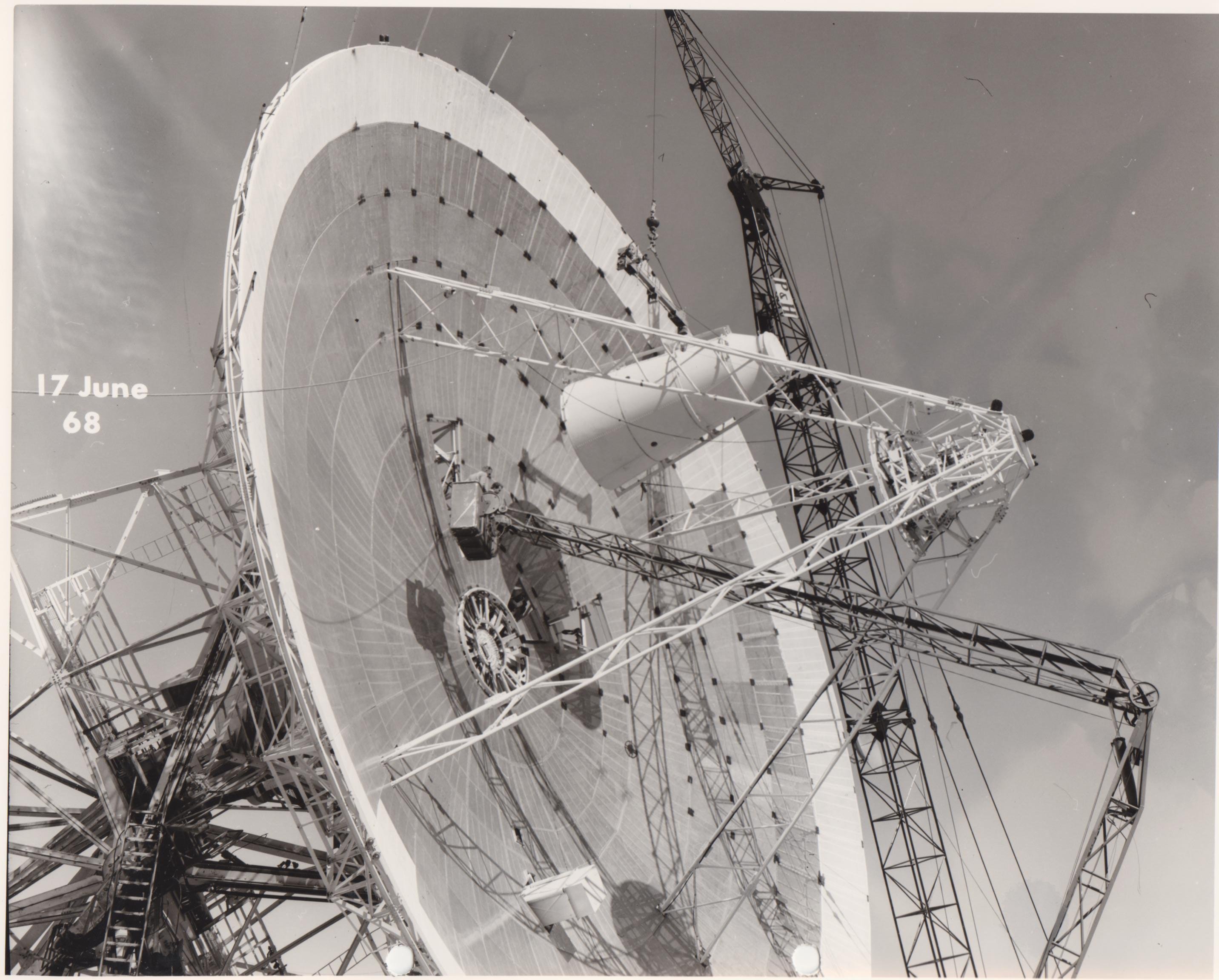
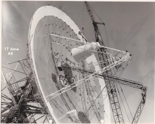
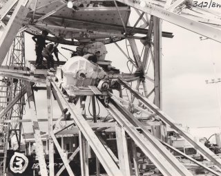
On 1968 June 17 a second Cassegrain cone change occurred - it is unclear
from the photo sequence if this is another removal, a
re-installation, or the installation of a new cone (there are two at
Hartebeesthoek).
Click on the image for large version
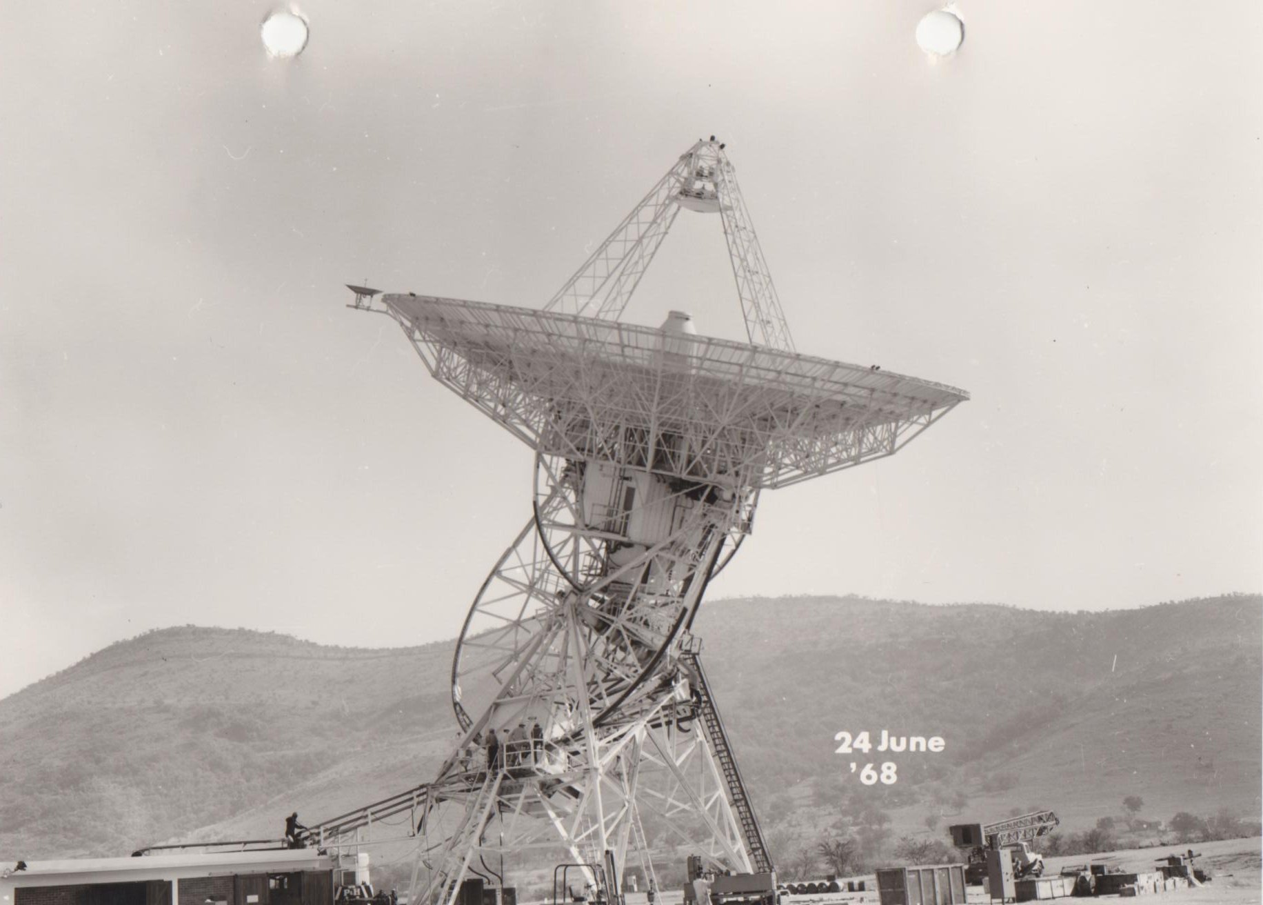
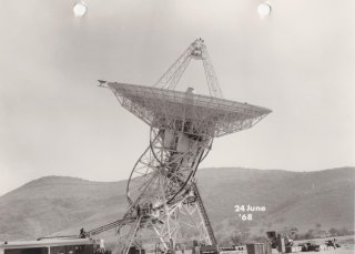
View of the antenna from the South East on 1968 June 24.
Click on the image for large version
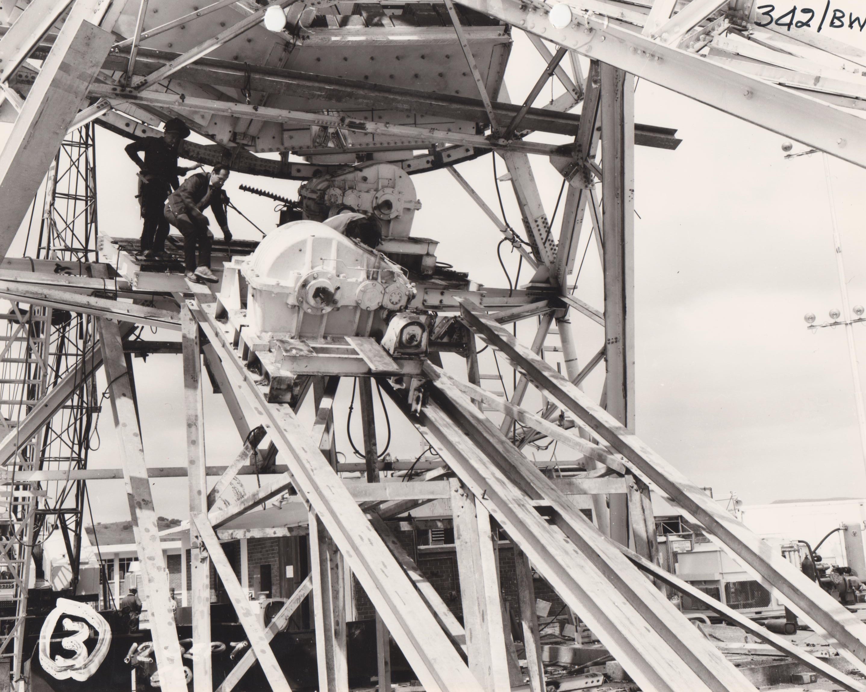
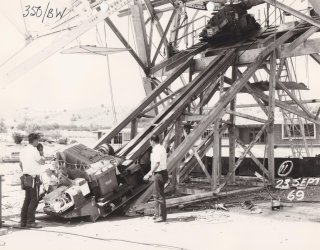
The Hour Angle gearboxes were removed on 1969 September 12.
Click on the image for large version
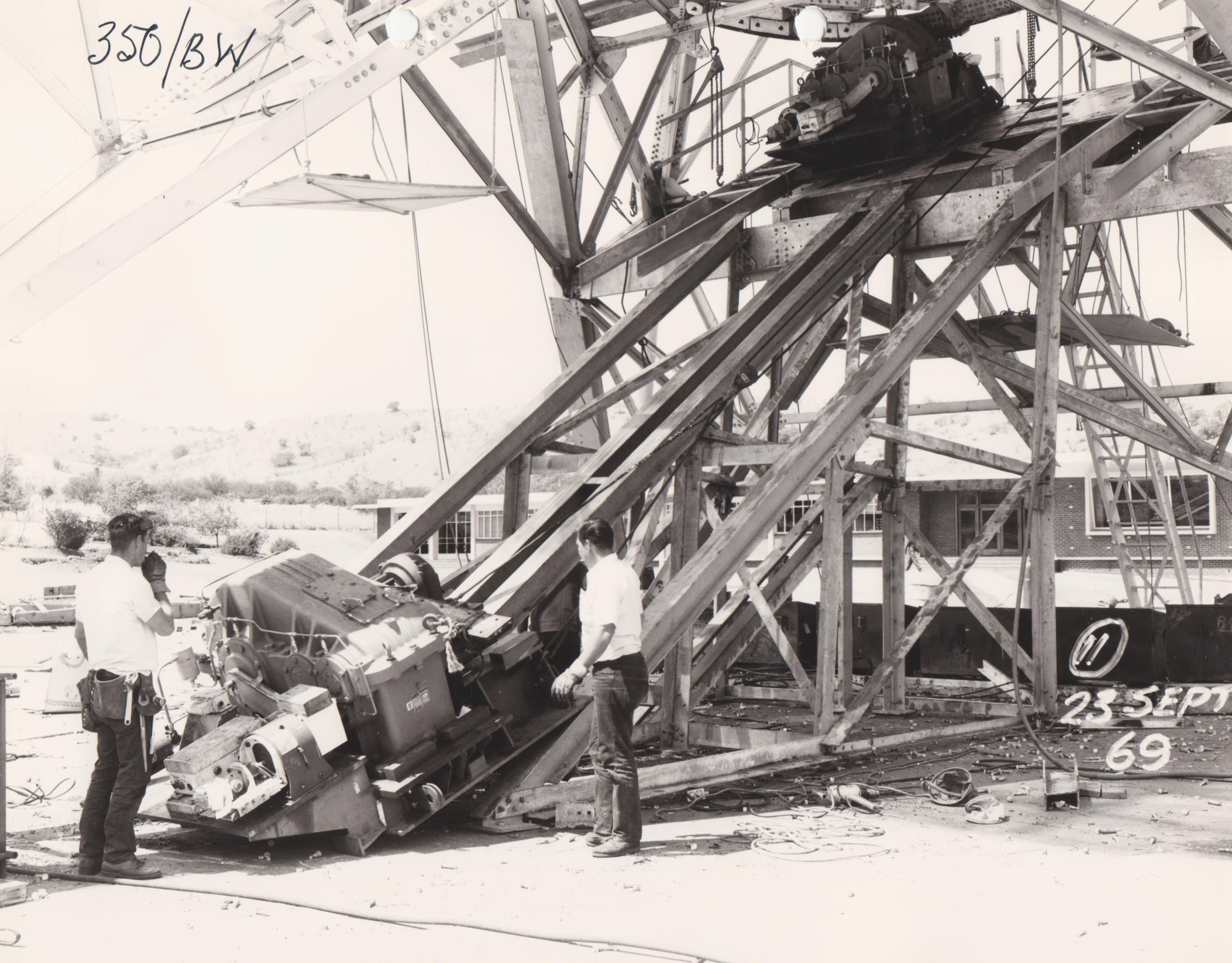
New Hour Angle gearboxes were installed on 1969 September 23.
Click on the image for large version
The "cherrypicker" (Hi-Ranger) being used to access the Dec Room, 1970
January 26.
Click on the image for large version
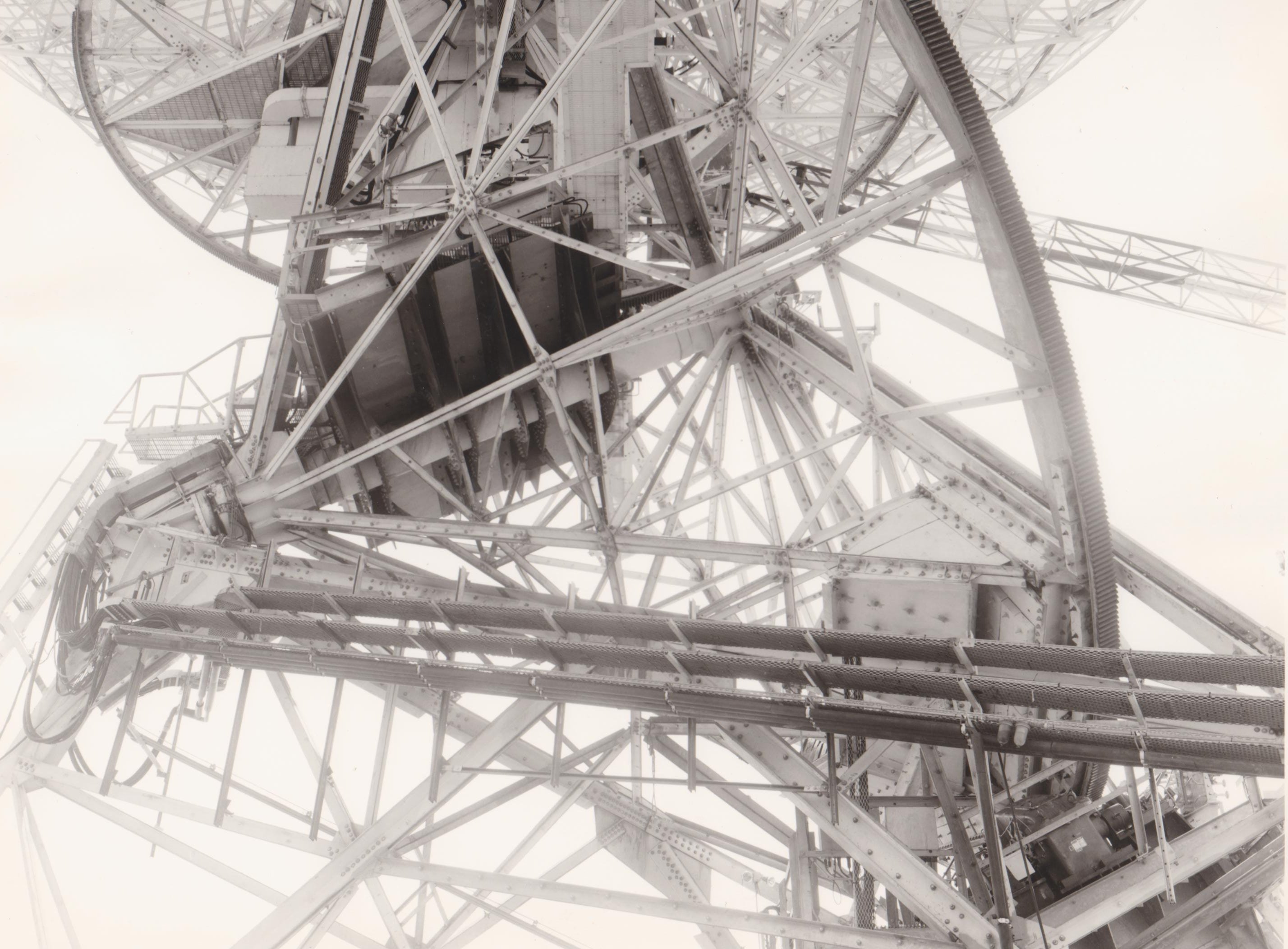
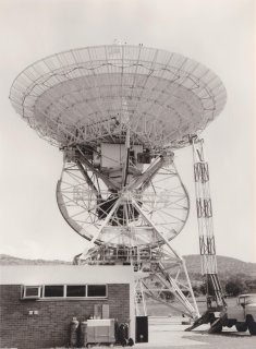
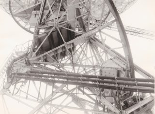
The unpainted ribs under the support platform for the Declination drive,
which is attached to the polar shaft, show that work has been carried out on
them, 1970 January 26. This picture is taken from the Western side of the
antenna.
Click on the image for large version
The antenna pointing far West on 1973 March 16.
Links
Back to History of
Deep Space Station 51 at Hartebeesthoek
Pictures of the construction of the antenna are shown here.
For more information, see: