home

HartRAO Home > HartRAO 26m Radio Telescope Details


HartRAO 26m Radio Telescope Details


Hartebeesthoek Location

Hartebeesthoek is located 65 kilometers north-west of Johannesburg, just within the provincial boundary of Gauteng. The nearest town, Krugersdorp, is 32 km distant. The telescope is situated in an isolated valley which affords protection from terrestial interference. See how to get to HartRAO.

26-m Telescope coordinatesAstronomicalGeodetic
Latitude 25 53' 14".4
25.887 deg.
South
-25 53' 23".1246
Longitude27 41' 05".2
27.685 deg.
East
+27 41' 07".107
Height above ellipsoid (WGS84) -1415.821m

Note that at Hartebeesthoek the geoid is 25.0m (World Geodetic System 1984 = WGS84) or 25.24m (Earth Gravity Model 1996 = EGM96) above the ellipsoid. The geoid is the equipotential surface of the Earth's gravity field which best represents global mean sea level, by least squares fitting.

The 26m telescope provides the Hartebeesthoek94 datum for South Africa.

VLBI Coordinates of the 26-metre Radio Telescope

The motion of the telescope has been determined from the geodetic VLBI network results by the Goddard Spaceflight Centre VLBI group. ITRF2005 position and velocity shown were obtained from ITRF solutions extraction. The Hart 26m telescope is DOMES 30302S001, cdp 7232.

Coordinate ITRF92, epoch 1988.0 ITRF96, epoch 1997.0 ITRF2005, epoch 2008/01/01
X +5085442.785m +5085442.780m +5085442.778m -0.0002m/y
Y +2668263.330m +2668263.483m +2668263.699m +0.0193m/y
Z -2768697.188m -2768697.034m -2768696.825m +0.0173m/y

26-metre Radio Telescope Specification

The radio telescope is an equatorially mounted 85 foot Cassegrain design built by Blaw Knox in 1961.

Diameter 25.9 m
Focal Ratio (f/D) 0.424
Surface Tolerance 0.5 mm rms
Wavelength Limit 1.3 cm
Feed System Cassegrain
Pointing Resolution 0.001 degrees
Repeatability 0.004 degrees
Slew Rate on each axis 0.5 deg/s

Notes:

  1. The hydraulic drive system was replaced by an electric drive during November 1998. Each axis is driven by a pair of 9 kW electric motors through reduction gearboxes. The two motors work in conjunction for high speed driving, and opposing each other in an anti-backlash arrangement at low speeds.
  2. The antenna surface comprises solid aluminium panels with a manufacturing rms error of ~0.25mm. Following the alignment of the panels using theodolite and steel tape, they were estimated to be set at zenith with an accuracy of ~0.5mm. Measured aperture efficiencies at short wavelengths indicate that this is approximately correct.
  3. The 26-m telescope operates under direct computer control by the PC/Debian Linux-based New Control Computer System.

Microwave Receivers on the 26-m telescope

Band <18 cm> <13 cm> <6 cm> <4.5 cm> <3.5 cm> <2.5 cm> <1.3 cm>
Feed horns 1 x circular 1 x circular 2 x diagonal(1) 1 x diagonal + cheesecutter polarizer (2) 2 x circular(1) 1 x circular 1 x circular
Polarization LCP & RCP LCP & RCP LCP & RCP LCP & RCP LCP & RCP LCP & RCP LCP & RCP
Amplifier cryogenic HEMT cryogenic HEMT cryogenic HEMT cryogenic HEMT cryogenic HEMT uncooled PHEMT uncooled
Standard frequency (MHz) 1666(2) 2280 5000 6670 8580 12180 23000
Lower frequency limit (MHz) 1608 2210 4650 6008 8180 12048 22000
Upper frequency limit (MHz) 1727 2450 5200 6682 8980 12216 24000
Receiver bandwidth (MHz)3 120 240 400 660 800 168 2000
Beamwidth: full width at half max. (degrees) 0.494 0.332 0.160 0.113 0.092 0.059 0.033
Beamwidth: between first nulls (degrees) 1.19 0.80 0.36 0.32 0.23 0.16 0.073
Minimum system temperature at Zenith (K) 394 44 50 57 60 95 220
Point Source Sensitivity per polarization (Jy/K/Pol)5 5.14 4.8 5.8 5.1 5.7 5.8 6.0
System Equivalent Flux Density per polarization (Jy/Pol)5 2004 210 290 290 340 670 1500
Observing parameters for the Hartebeesthoek 26-metre radio telescope

Notes:

  1. The 6 and 3.5 cm receivers are dual-feed systems permitting Dicke-switched radiometry. The effective response of the receiver - radiometer system at 6 cm is 4840 - 5100 MHz, ie 260 MHz bandwidth centred on 4970 MHz. At 3.5 cm the effective radiometry centre frequency is 8400 MHz.
  2. The 18 cm receiver can operate unfiltered, or with computer-selectable filters centred on 1612, 1650, 1666 and 1720 MHz.
  3. For radiometry, the IF signal can be used unfiltered, or passed through 4, 8, 16 or 32 MHz bandwidth filters to control the bandwidth or exclude interfering signals. The maximum bandwidth is not necessarily usable. At 18cm 16MHz bandwidth is typically usable, and 32MHz at 13cm, owing to RFI. The detectors in the radiometers have a 3dB bandwidth of about 450MHz.
  4. For the 18 cm receiver operating with the subreflector tilted through half the angle that the feed is offset from the axis, to maximise efficiency. For the higher frequencies they apply at small zenith angles and with low atmospheric water vapour.
  5. Performance measured after the alignment of the new surface panels and realignment of the subreflector, 2004 Oct 15. These values are a guide only, as performance of each system depends on the frequency and bandwidth in use and the observing conditions.

Instrumentation

Observing limits for the 26-m Hartebeesthoek Radio Telescope

Being an equatorially mounted telescope, the elevation limit is not a simple function. It is constrained by mechanical limits in the south and north, and the local topography in the north-east and south-west.

The algorithm for the hour angle limits as a function of antenna declination, for angles specified in degrees, is given below as pseudocode.

Note that the local terrain results in an asymmetric horizon.

The absolute northern declination limit is +45 degrees.

      IF HA LESS THAN 0.0 THEN
*         limit command HA in the east
*         southern HA limit
          HALIM = -88.0 
*         HA limit decreases moving north
          IF (DEC GREATER THAN -15.0) HALIM = 0.45*DEC - 81.25
          IF (DEC GREATER THAN +25.0) HALIM = DEC - 95.0
      ELSE
*         HA greater than zero, limit command HA in the west
*         southern HA limit
          HALIM = +88.0 
*         HA limit decreases moving north
          IF (DEC GREATER THAN -5.0) HALIM = -0.3*DEC + 86.5
          IF (DEC GREATER THAN +5.0) HALIM = -DEC + 90.0
      END IF
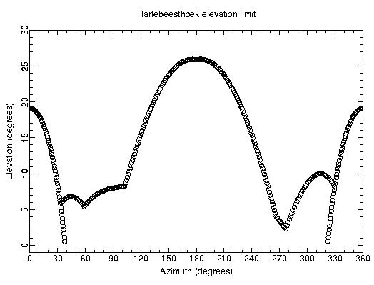
The elevation limit as a function of azimuth is shown below.

HRAO horizon