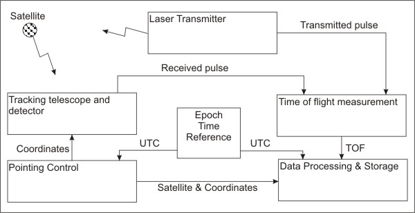
Figure 1: A basic SLR system diagram
These pages provide basic to intermediate level information on the Hartebeesthoek Satellite Laser Ranger (SLR).
This homepage first gives a general introduction to SLR basics and then gives an overview of the MOBLAS 6 system used by HartRAO.
At no time should this information be seen as an accurate technical representation of the system, but only as a guide to basic subsystem functionality and subsystem interconnections.
Satellite tracking involves reflecting laser pulses off special mirrors on telescopes and measuring the time of flight of these pulses.
To track a satellite successfully one must simultaneously obtain the following information:
The satellite being tracked
Pointing coordinates
Time at instant of successful track
Time of flight of laser pulse (from which distance is calculated)
This information constitutes all the necessary components for Data Processing & Storage as seen in the basic SLR diagram, figure 1.
Figure
1: A basic SLR system diagram
Accurate timing is the most important aspect, for both the instantaneous time according to UTC and the time interval measurement for the time of flight of the laser pulse. The Epoch time reference consists of a very accurate clock, usually more accurate than 10¹² parts of a second, which supplies precise time signals to both the Pointing Control and the Data Processing & Storage subsystems.
The Pointing Control subsystem use the time information together with estimated orbital data of the specific satellite to calculate the estimated pointing coordinates. The satellite location is usually quite close to this and by scanning through a certain range of offsets the satellite can be found.
The laser exit path and the telescope are co-mounted so that they point in exactly the same direction. If a laser pulse is reflected against one of the retroreflectors on the telescope the light returns along the same path towards the telescope and ultimately the detector.
A successful detection of the returned laser pulse implies that the satellite position has been acquired and a data-point can be sent to the Data Processing & Storage subsystem. Since satellite orbits range from ~ 500 km to ~ 22 000 km, the time of flight of the laser pulses are about 3.3 to 147 ms (from emission till detection). Also keep in mind that for millimeter precision one must be able to meassure accurately down to the 3.3 ps level!
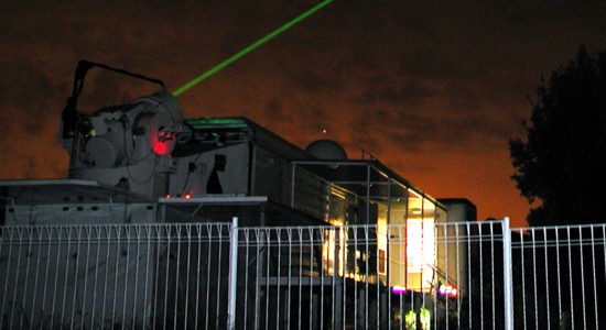
Photo
of the MOBLAS 6 in action at HartRAO
The SLR at HartRAO is NASA's MOBLAS 6 Station. It was inaugurated on 20 November 2000 and the flyers distributed during the event can be viewed here. It is part of the NASA network of the ILRS (International Laser Ranging Service).
The SLR system consists of several subsystems that are interconnected:
Laser: The laser table and all associated power supplies and electronics
Tracking and Mount Control (T&MC): This includes the telescope optics and controls the pointing
Data Measurement (DMS): Measurement and Laser Ranger Controller (LRC) Logic
Timing: Produces timing and synchronisation signals according UTC
Controller: PC controlling all the subsystems
Processor: PC for processing data and sending / receiving of files
Safety: Safety features integrated into the system at various places
The various subsystems are all housed in the Mobile Optical Mount System (MOMS) van and a diagram depicting the basic system interconnetions is showed in figure 2. The MOMS van is supplied with 208V AC (3 phase) and 120V AC (single-phase) at 60 Hz. Since many acronyms are used, it is recommended that the Acronym List be opened (opens in a seperate window).
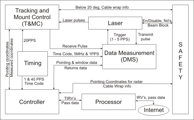
Figure 2: Interactive diagram of the basic MOBLAS 6 Subsystem
interconnections
The Timing subsystem is the heart of the SLR- it provides pulses to coordinate events as well as Time Code, calibrated to UTC, in NASA 36-bit format to various subsystems.
The Processor subsystem performs onsite data analysis. It receives predicted satellite orbital data in the form of Inter-Range Vectors (IRV's) from headquarters via the internet, generate local Tuned IRV's (TIV's) and pass this data to the Controller subsystem. After a pass it receives pass data from the Controller, puts it in appropriate formats and performs post-pass analyses. The processed data is then transmitted back to headquarters.
The Controller subsystem aims the tracking optics and tracks targets using the data received from the Processor and computes and records ranging data. It also runs diagnostics on the system.
Tracking and Mount Control steers the telescope in the required direction, transmits the laser pulses in the same direction and capture the laser returns, sending receive pulses to the DMS.
The Laser receives trigger pulses from the DMS to fire and sends a transmitted pulse back to the DMS. The laser pulse is directed by a coude mirror train to the T&MC.
The Data Measurement subsystem detect, measure, condition, manipulate and display received pulses. It also provides the required outputs to the Controller for ranging computations and recording.
Overall system safety is handled by the Safety subsystem. It obtains data from various parts of the system and once an unsafe condition is detected it disables the appropriate sections.
Figure 3 provides a MOBLAS 6 Ranging System simplified block diagram. The pages corresponding to the various subsystems also contains the location of certain devices as an MRU number (eg. MRU 2A1 for the Interlock) as well as photos taken of the various devices. For a diagram showing the general physical layout in the MOMS van, click here (opens a new window). The manuals of the MOBLAS 6 system are listed in a document labelled as NSLR-01-0002. References to the manuals of specific components are also made in these pages and generally start with NSLR, CDSLR, ME, MM or EC. A page containing more complete information on manuals can be found here (opens a new window).
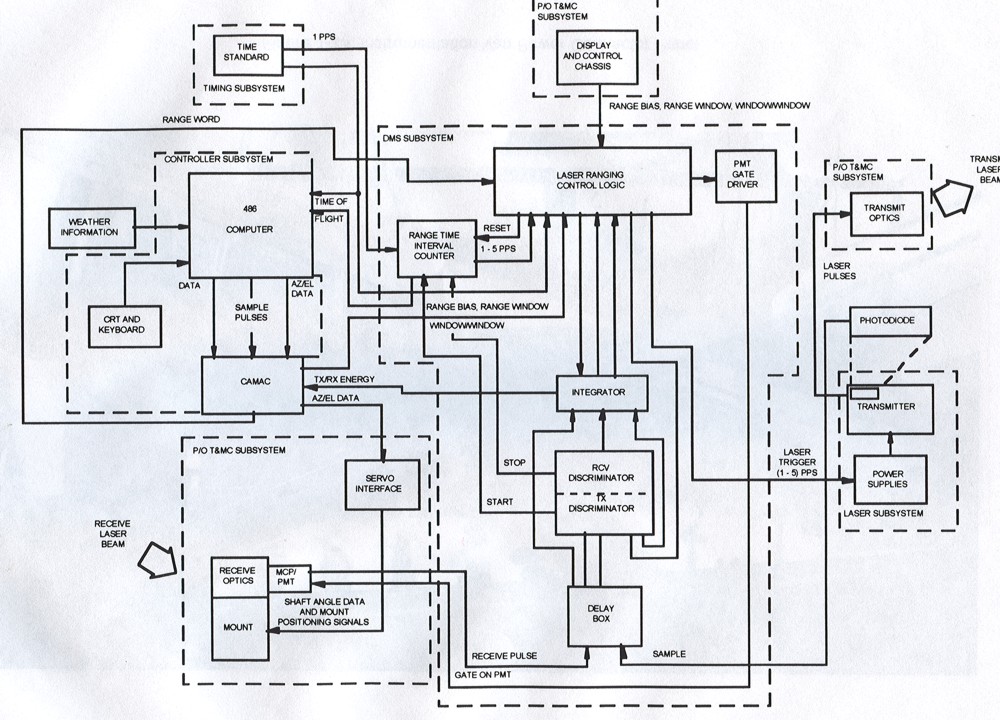
Figure
3: MOBLAS 6 Ranging System Simplified Block Diagram.